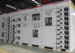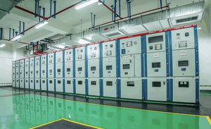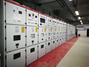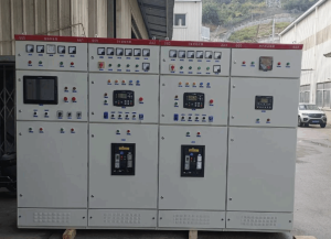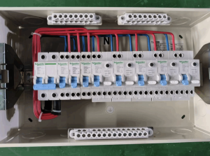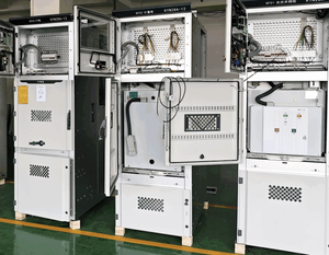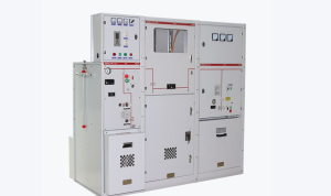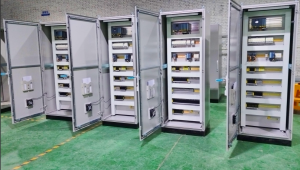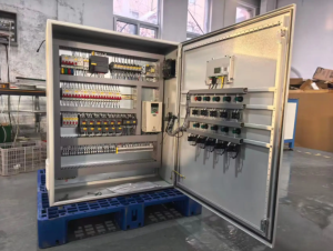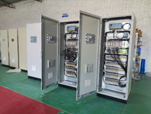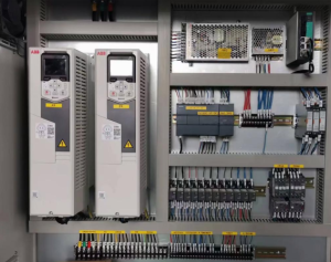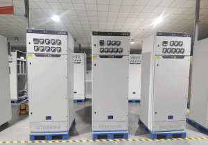
Substation switchgear represents core integrated electrical equipment within power transmission and distribution systems at substations. It undertakes critical tasks including power distribution, load switching, fault isolation and short-circuit protection.
Many engineering professionals encounter numerous questions in the early stages of project development. What categories are covered by substation switchgear? How should engineers select between Air-Insulated Switchgear (AIS) and Gas-Insulated Switchgear (GIS)? What are the differences in applicable scenarios for switchgear at different voltage levels? Which international standards must be followed for equipment selection? What standardized procedures govern routine operation, maintenance and fault handling?
This article systematically organizes professional knowledge of substation switchgear, ranging from basic definitions and equipment classification to selection schemes, construction acceptance and long-term operation and maintenance. Combined with application scenarios for new energy substations, it delivers comprehensive technical references.
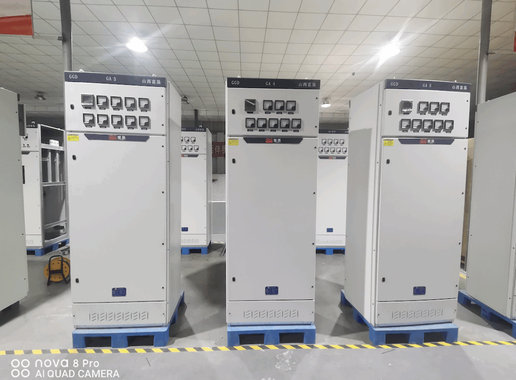
What is a Substation Switchgear Cabinet?
Substation switchgear is integrated switch equipment assembled with circuit breakers, disconnectors, earthing switches, instrument transformers, busbars, operating mechanisms and secondary control & protection components. Installed within the distribution areas of substations, it controls, protects and monitors power circuits.
1.1 Four Core Functions
- Normal load switching: Complete closing and opening operations for transmission circuits and transformer loops in response to operational requirements.
- Fault protection and interruption: When short-circuit or overload faults occur in the system, the circuit breaker rapidly disconnects the faulty circuit to prevent accident escalation.
- Electrical isolation: Create visible breaking points via disconnectors to guarantee personnel safety during equipment maintenance.
- Power monitoring and control: Collect operational parameters in coordination with current and voltage transformers, and interface with relay protection devices.
1.2 Core Internal Components of Switchgear
A complete set of substation switchgear mainly consists of vacuum circuit breakers (VCB), disconnectors, earthing switches, current/voltage transformers, busbar systems, surge arresters and secondary protection & measurement control devices.
2. Main Classification of Substation Switchgear
Substation switchgear is classified primarily by voltage rating and insulation structure.
2.1 Classification by Voltage Level
Low-Voltage (LV) Switchgear
Typically rated at 1 kV and below. It is deployed for substation auxiliary power systems to supply power to DC panels, cooling systems, lighting, monitoring equipment, and is excluded from main power transmission circuits.
Medium-Voltage (MV) Switchgear
Common voltage ratings include 10 kV, 20 kV and 35 kV. Widely adopted in urban distribution network substations and distributed new energy step-up substations. Vacuum circuit breakers (VCB) serve as the mainstream configuration.
High-Voltage (HV) Switchgear
Covers 66 kV, 110 kV, 220 kV and higher voltage classes. Deployed in regional hub substations to undertake long-distance power transmission.
2.2 Classification by Insulation Structure: AIS versus GIS Switchgear
These two equipment types are most frequently compared during substation project selection.
Air-Insulated Switchgear (AIS)
Ambient air serves as the insulation medium between phases and to earth. It features lower procurement costs and convenient maintenance. Its disadvantages include a larger footprint and certain requirements for on-site cleanliness. It is suitable for inland substations with sufficient land space and favorable climatic conditions.
Gas-Insulated Switchgear (GIS)
Core live components are enclosed within metallic enclosures, using insulating gas for insulation and arc extinction. Featuring a compact layout and small footprint, GIS is minimally affected by external dust, humidity and salt spray. It applies to compact urban substations, coastal salt-spray regions and offshore wind power substations. Drawbacks include higher equipment procurement costs, together with elevated technical requirements for gas leakage detection and on-site repairs.
3. Operating Principle of Substation Switchgear
Electric power enters the switchgear through main busbars. Under normal operating conditions, circuit breakers remain closed to transmit electricity to downstream transformers or outgoing feeders.
System monitoring devices continuously collect circuit current and voltage data. Upon short-circuit or overload faults, relay protection devices immediately issue tripping commands. The arc-extinguishing assembly inside the circuit breaker rapidly quenches electric arcs and interrupts fault currents.
Prior to equipment maintenance, circuit breakers are opened; disconnectors are operated to form visible isolation breaks, and earthing switches are closed to discharge residual charges, ensuring personal safety when technicians access circuits. Mechanical and electrical interlocks are equipped across the whole assembly to prevent hazardous maloperations such as incorrect closing/opening and opening disconnectors under load.
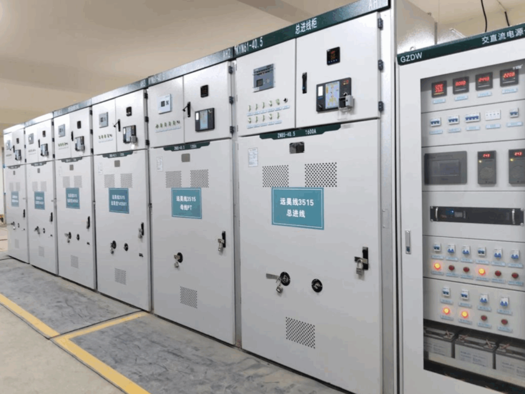
4. Key Selection Criteria for Substation Switchgear
Equipment selection for engineering projects cannot rely solely on voltage parameters; long-term operating conditions require comprehensive evaluation.
4.1 Basic Electrical Parameters
Rated voltage, rated current, rated short-time withstand current (short-circuit breaking capacity) and insulation level must match the design standards of the power grid system. Insufficient short-circuit parameters will directly lead to equipment damage during faults.
4.2 On-Site Environmental Conditions
- Space constraints: GIS is prioritized for sites with limited land area; AIS is an option for sites with ample space.
- Operating conditions: Sealed GIS equipment is preferred for coastal areas, mining zones, high-humidity and high-dust environments.
- Altitude correction: Outer insulation parameters require modification for high-altitude sites to avoid insulation breakdown.
4.3 Long-Term Capacity Expansion Requirements
Planned substations shall reserve space for load growth. Expansion interfaces shall be reserved for switchgear busbar rated current and bays to avoid complete equipment replacement after short-term retrofits.
4.4 Balance Between Capital Expense and Full-Life-Cycle Cost
AIS delivers low initial investment yet occupies larger land area and demands heavy outdoor maintenance workload. GIS commands higher purchase prices but features longer maintenance cycles and lower failure rates. For large-scale long-term projects, full-life-cycle cost analysis is recommended rather than direct comparison of initial quotations only.
5. Installation, Operation and Maintenance Guidelines for Substation Switchgear
5.1 Installation Specifications
Carry out horizontal calibration of base channel steel and reliable earthing of cabinet bodies; apply manufacturer-specified torque standards for busbar connections. Installation of GIS equipment imposes strict control over dust and humidity; a dust-free operation shelter must be constructed for assembly work.
5.2 Pre-Commissioning Test Items
Insulation resistance test, contact resistance test, power frequency withstand voltage test, interlock function test and protection group trip test. For GIS equipment, additional tests including gas moisture measurement and air tightness leakage detection are required. Grid connection and power transmission can only proceed after all tests pass.
5.3 Routine Maintenance and Fault Troubleshooting
- Regular patrol inspection: Check for overheating and corrosion, monitor gas pressure, and verify the connection status of secondary circuits.
- Periodic preventive tests: Conduct tests following maintenance regulation cycles.
- Common faults: Contact overheating, mechanism failure to close/trip, gas leakage, instrument transformer abnormalities and unintended protection tripping.
6. Application Solutions of Substation Switchgear
6.1 Traditional Power Grid Hub Substations
A combined scheme of AIS and GIS is commonly adopted for high-voltage levels. Priority is given to power supply reliability to satisfy continuous large-load transmission demands, with complete remote monitoring interfaces reserved.
6.2 Wind & PV New Energy Step-Up Substations
New energy power plants face voltage fluctuations and harmonic interference. Switchgear must adapt to grid-connected operating conditions of inverters with enhanced protection configurations. Compact GIS equipment is widely selected for mountainous and tidal flat new energy projects to save land occupation.
6.3 Industrial Captive Power Substations
Medium-voltage switchgear dominates such scenarios. For high-load industrial loads such as smelting and chemical production, short-circuit withstand capacity is upgraded with anti-internal arc fault designs equipped.
Frequently Asked Questions
Q1: What are the core differences between medium-voltage and high-voltage substation switchgear?
Core distinctions lie in rated voltage, short-circuit breaking parameters, insulation structures and application hierarchy. Medium-voltage switchgear serves terminal power distribution, while high-voltage switchgear undertakes main trunk power transmission for regional grids with higher safety margin standards for insulation design.
Q2: Should GIS or AIS switchgear be selected for newly built substations?
GIS is prioritized for space-restricted sites, coastal salt-spray areas and underground urban substations. AIS is suitable for inland open sites, budget-limited projects and facilities requiring frequent maintenance access.
Q3: How frequently shall preventive maintenance be carried out on substation switchgear?
Schedules are determined by voltage level, operating environment and manufacturer technical guidelines. Conventional medium-voltage equipment requires preventive tests every 1 to 3 years; maintenance cycles of high-voltage GIS equipment can be appropriately extended based on online monitoring data.
Conclusion
As barrier equipment within power transmission and distribution systems, negligence in any link including selection, installation and maintenance of substation switchgear may trigger power outages and even safety hazards. During project design, engineers shall conduct comprehensive equipment selection combining system parameters, geographical environment and long-term maintenance conditions, and strictly comply with IEC standards and local industrial specifications.
References
IEC 62271-1:2017 High-voltage switchgear and controlgear – Part 1: Common specifications
IEC 62271-203: Gas-insulated switchgear (GIS)
IEEE C37.100 Standard for High-Voltage Switchgear