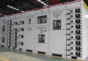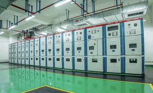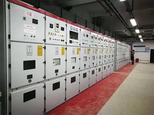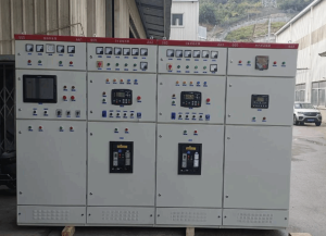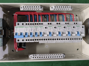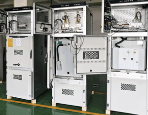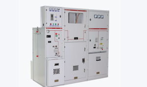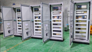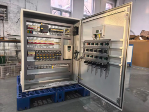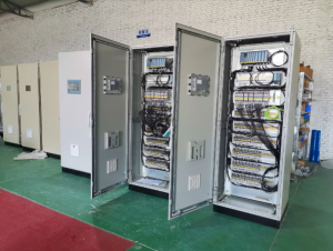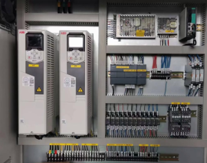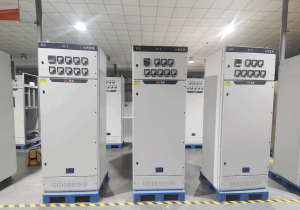
In industrial power distribution, critical infrastructure and commercial power‑supply systems, Power Control Switchgear (also known as Power Control Centre, PCC) serves as the core hub for power source management, fault isolation and load dispatching. It not only determines power‑supply continuity and reliability but also bears a direct bearing on operational safety and the total life‑cycle cost of equipment. This article provides a comprehensive overview of power control switchgear, covering its definition, working principle, selection methodology and application scenarios.
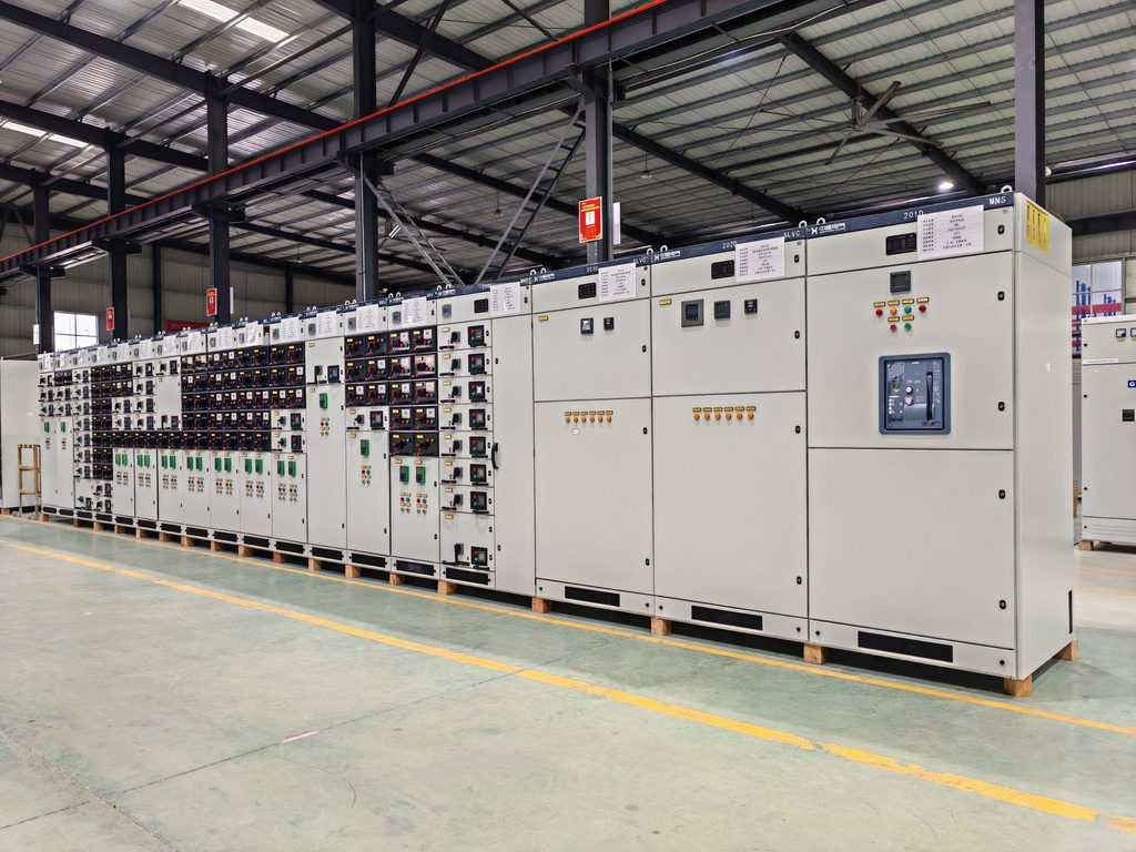
1. What is Power Control Switchgear
Power control switchgear is a complete set of electrical equipment integrating switching devices, protection units, measuring instruments and control modules. It receives incoming power from utility grids or generator sets and performs power distribution, control, protection and monitoring. It acts as the critical node linking upstream power sources to downstream loads within power supply and distribution systems.
Per IEC 61439‑1, low‑voltage power control switchgear falls under the category of low‑voltage switchgear and control‑gear assemblies, with rated AC voltage up to 1 000 V and rated DC voltage up to 1 500 V. Medium‑ and high‑voltage variants comply with the IEC 62271 series of standards for distribution applications above 1 kV.
Compared with general‑purpose distribution equipment, power control switchgear features centralised power‑source‑side management and advanced fault protection. It delivers enhanced short‑circuit withstand capability, sophisticated relay protection logic, and complex control functions such as multi‑source paralleling and automatic transfer. It is typically installed at the incoming section of distribution systems and upstream of critical loads.
Four core values are highlighted below:
- Rapid fault isolation: Upon detecting short‑circuit, overload, undervoltage and other abnormal conditions, it trips the faulty circuit within milliseconds to prevent fault propagation across the whole system.
- Continuity of power supply: It supports automatic transfer between dual power sources and generator paralleling to guarantee uninterrupted power for priority‑class loads.
- Refined power management: It enables circuit‑level monitoring of current, voltage and power, supporting energy consumption statistics and load dispatching.
- Personnel and equipment safety: Cabinet‑level protection, electrical interlocks and mechanical interlocks prevent operators from accessing live parts and mitigate arc‑flash hazards.
2. Working Principle of Power Control Switchgear
Power control switchgear operates on dual logic chains: power energy transmission and protection & control. Four key functional stages are described as follows.
2.1 Power Incoming and Busbar Distribution
Upstream power sources such as utility transformers and diesel generator sets feed power into the main busbar system via incoming circuit breakers. As the power‑distribution backbone, busbars deliver electricity to individual outgoing circuits. Copper busbars are commonly adopted, with cross‑sections sized according to rated current to ensure compliance with temperature‑rise limits during continuous operation.
2.2 Protection and Control Execution
Each outgoing circuit is fitted with dedicated protection and switching components:
- Relay protection devices acquire real‑time current and voltage signals and compare measured values against preset protection settings (long‑time overload delay, short‑time short‑circuit delay, instantaneous short‑circuit trip, earth‑fault protection, etc.).
- When abnormal operating conditions occur, protection units send tripping commands to actuate circuit breakers and disconnect faulty circuits.
- Control circuits respond to local or remote commands to perform circuit‑breaker closing/tripping, power‑source transfer and interlock protection logic.
2.3 Typical Operating Modes
- Normal power‑supply mode: Power flows stably through incoming switches, busbars and outgoing switches to end loads, while monitoring systems track real‑time operational parameters.
- Fault‑protection mode: In the event of a downstream short‑circuit, the corresponding circuit breaker trips rapidly. Main busbars and other circuits remain energised to achieve selective protection.
- Dual‑source transfer mode: Upon utility‑grid failure, the control system automatically opens the utility incoming breaker and closes the standby‑source or generator‑input breaker for seamless load power transfer.
- Parallel‑operation mode: Multiple generator sets or power sources are synchronised and paralleled onto the common busbar via synchronisation controllers to share total loads and boost power‑supply capacity and redundancy.
2.4 Signal Feedback and Human‑Machine Interface
Meters, indicator lamps and touch‑screen HMI display operating parameters and equipment status, with audible‑visual alarms triggered on faults. Intelligent models are equipped with communication interfaces to upload data to distribution monitoring platforms for remote operation and maintenance.
3. Main Components of Power Control Switchgear
A complete power control switchgear assembly consists of four major groups: primary power‑circuit units, control‑and‑protection units, auxiliary functional units, and cabinet structures.
3.1 Primary Power‑Circuit Units
These components handle power transmission and circuit breaking and form the power backbone:
- Incoming circuit breaker: Air Circuit Breaker (ACB) is widely deployed as the main switch for system switching and global protection. Rated current ranges from 800 A to 6 300 A with LSIG four‑segment protection functions.
- Outgoing circuit breaker: Air‑circuit breakers serve high‑capacity circuits, while Moulded‑Case Circuit Breakers (MCCB) are used for medium‑ and low‑capacity branches for individual‑circuit switching and protection.
- Busbar system: Comprises horizontal main busbars and vertical branch busbars for power distribution, designed to satisfy short‑time withstand‑current and temperature‑rise requirements.
- Instrument transformers: Current Transformers (CT) and Voltage Transformers (PT) convert high‑magnitude current and voltage into standard signals for protection and metering devices.
- Disconnector / Earthing switch: Provides visible isolation points for maintenance work to safeguard service personnel; mandatory for medium‑ and high‑voltage switchgear.
3.2 Control‑and‑Protection Units (Secondary Circuits)
Responsible for logical control, status monitoring and fault protection:
- Relay protection devices: Multi‑function protective relays and motor‑protection relays implement overload, short‑circuit, earth‑fault, undervoltage and other protection features.
- Controllers: PLCs, dual‑power transfer controllers and synchronisation‑paralleling controllers execute advanced logic including automatic source transfer and generator grid‑connection.
- Operating mechanisms: Manual or motor‑driven operating mechanisms for circuit‑breaker closing and tripping.
- Measuring instruments: Ammeters, voltmeters and multi‑function power meters display real‑time operational parameters.
3.3 Auxiliary Functional Units
- Surge Protective Device (SPD): Suppresses lightning‑induced and switching over‑voltages to safeguard sensitive internal components.
- Cooling system: Natural ventilation, forced‑air fans or cabinet air‑conditioners maintain internal temperature within component allowable limits.
- Cabinet lighting, heating and dehumidification units: Counteracts low‑temperature and high‑humidity conditions to prevent insulation degradation caused by condensation.
- Communication modules: Supports Modbus, Profibus, Ethernet and other industrial protocols to enable remote monitoring.
3.4 Cabinet and Enclosure Structures
- Cabinets are mostly assembled from cold‑rolled steel or aluzinc steel plates with sufficient mechanical strength and arc‑resistance performance.
- Segregated compartments (breaker compartment, busbar compartment, cable compartment and instrument compartment) achieve physical fault containment.
- Ingress‑protection ratings range from IP30 for standard indoor environments up to IP65 for harsh outdoor applications, selected according to installation conditions.
- Mechanical and electrical interlocks are fitted to prevent mis‑operation and satisfy the “five‑prevention” safety requirements.
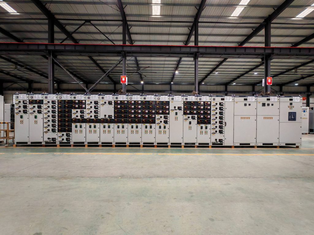
4. Key Application Scenarios
Power control switchgear is standard equipment for all medium‑to‑large‑scale power‑supply systems. Major application sectors cover six categories below.
4.1 Data Centres
As a core component of Tier‑rated data‑centre power infrastructures, power control switchgear manages utility incoming feeds, diesel‑generator paralleling and dual‑busbar distribution. It is required to deliver 99.999 % power‑supply availability, equipped with high‑precision relay protection and intelligent monitoring to ensure uninterrupted operation of IT and cooling loads.
4.2 Industrial Manufacturing
Main step‑down substations and workshop distribution rooms in steel, chemical, automotive and electronics plants adopt power control switchgear as central hardware for concentrated management of production‑line dynamic loads, covering motors, variable‑frequency drives and heating equipment to sustain continuous manufacturing and mitigate downtime losses.
4.3 Healthcare Facilities
Grade‑A hospitals and emergency centres impose strict continuity‑of‑power requirements for priority loads including operating theatres, ICUs and imaging systems. Power control switchgear works in tandem with UPS and generator sets to realise seamless multi‑source transfer and guarantee stable operation of medical apparatus.
4.4 New‑Energy Power Stations
Medium‑ and high‑voltage power control switchgear is deployed at grid‑connection points and step‑up substations of photovoltaic, wind‑power and energy‑storage plants. It performs power collection, grid‑connection protection and fault isolation while accommodating output volatility of renewable energy and complying with grid‑connection codes.
4.5 Commercial Complexes and High‑Rise Buildings
Power control switchgear is installed at main incoming sections of large shopping malls, office towers and super‑high‑rise buildings. It handles gross energy metering, hierarchical power distribution and priority power feeding for fire‑safety loads, balancing power‑supply safety and energy‑efficiency management.
4.6 Critical Public Infrastructure
Rail transit, airports, seaports, waterworks and wastewater‑treatment plants rely on power control switchgear for power‑supply protection of core process equipment, with configurations adapted to demanding outdoor, humid and dusty operating environments.
5. Selection Guide for Power Control Switchgear
Proper equipment selection guarantees field adaptability and long‑term stable performance. Evaluation shall cover electrical parameters, functional requirements, installation environment and regulatory compliance.
5.1 Determine Core Electrical Parameters
- Rated voltage: Matched to system voltage. Common low‑voltage ratings: 380 V / 400 V / 690 V; common medium‑voltage ratings: 10 kV / 35 kV.
- Rated current: Rated current of main incoming breakers shall exceed total calculated system current, with a 1.2‑to‑1.5‑times design margin to avoid excessive temperature rise under continuous full‑load operation.
- Short‑circuit withstand current: Specified according to system short‑circuit capacity. Requirements cover 1‑second short‑time withstand current (Icw) and peak withstand current (Ipk) to prevent mechanical cabinet damage during short‑circuit events.
- Breaking capacity: The rated short‑circuit breaking capacity of circuit breakers must exceed the maximum prospective short‑circuit current of the installation system.
5.2 Match Functional Requirements
- Where dual‑utility feeds or standby generators exist, confirm whether automatic transfer and synchronisation‑paralleling functions are required.
- Intelligence requirements: Evaluate needs for remote monitoring, energy metering, fault‑recording and cloud‑platform connectivity.
- Operation modes: Local manual operation, motor‑driven operation or full remote automatic control.
5.3 Adapt to Installation Environments
- Installation location: IP30 / IP40 for indoor applications; minimum IP54 plus rain‑proof, sun‑shielding and anti‑condensation design for outdoor installations.
- Ambient temperature and humidity: High‑temperature, high‑humidity, high‑altitude and heavily polluted sites require enhanced cooling, anti‑corrosion and dehumidification configurations.
- Installation footprint: Choose fixed‑type or draw‑out‑type structures based on site dimensions; verify cabinet depth and service‑aisle width.
5.4 Compliance and Standard Requirements
- International projects: Comply with IEC 61439 (low‑voltage) and IEC 62271 (medium‑ and high‑voltage).
- North‑American projects: Meet UL 891 (Low‑Voltage Dead‑Front Switchboards), UL 1558 (Low‑Voltage Switchgear) and NEC requirements.
- Domestic Chinese projects: Follow GB 7251 and GB 3906, plus industry‑specific specifications for specialised sectors.
5.5 Total Life‑Cycle Cost Considerations
- Evaluate not only procurement costs but also installation expenditure, maintenance expenses, spare‑part interoperability and service life.
- Prioritise Type‑Test‑Approved (TTA) assemblies with fully validated performance and safety credentials.
- Although modular and draw‑out constructions carry higher upfront costs, they simplify inspection and repair and reduce downtime‑related losses.
Selection Check‑List: Rated voltage, rated current, short‑circuit withstand current, ingress‑protection rating, incoming/outgoing cable arrangement, quantity of circuits, protection‑function configuration, communication protocols, applicable standards, installation dimensions.
Frequently Asked Questions
Q1: What are the main functions of power control switchgear?
It centrally controls, distributes and protects power‑supply systems, enables fast fault isolation and ensures power‑supply continuity. Meanwhile, it monitors electrical parameters and supplies data for distribution‑system operation and maintenance. It functions as the safety and dispatching hub of power‑supply‑and‑distribution installations.
Q2: Are power control switchgear and general‑purpose distribution switchgear identical?
No. Power control switchgear is designed for upstream incoming‑side master control and advanced protection, featuring stronger short‑circuit withstand capability, comprehensive protection suites and complex multi‑source paralleling functions. General‑purpose distribution switchgear serves downstream branch‑level power distribution with simpler construction and lower capital cost.
Q3: What is the typical service life of power control switchgear?
Under proper maintenance and favourable ambient conditions, low‑voltage power‑control‑switchgear enclosures can last 20‑30 years. Core switching components such as circuit breakers achieve 10‑20 years of service life, subject to operating cycles. Medium‑ and high‑voltage switchgear generally delivers a service life exceeding 25 years. Scheduled maintenance effectively extends equipment service life.
Q4: Can power control switchgear be used for generator paralleling?
Yes. Dedicated paralleling‑type power control switchgear is fitted with synchronism check units, load‑sharing controllers and reverse‑power protection. It supports automatic paralleling of multiple diesel generator sets and is widely adopted in data centres, hospitals and other sites requiring large‑capacity standby power sources.
Q5: What safety standards shall power control switchgear satisfy?
Global standards: IEC 61439 series for low‑voltage equipment, IEC 62271‑100 for high‑voltage switchgear. North‑American standards: UL 891 and UL 1558. Chinese national standards: GB 7251 (low‑voltage assemblies) and GB 3906 (3.6 kV‑40.5 kV a.c. metal‑enclosed switchgear), alongside general distribution‑safety codes and sector‑specific requirements.
Conclusion
As the core hub of power‑supply‑and‑distribution systems, power control switchgear’s selection and maintenance directly determine the reliability and safety of entire power networks. Rigorous professional judgement is required throughout all phases: parameter matching and regulatory compliance in the project‑definition stage, standard‑compliant commissioning during installation, and life‑cycle operation‑and‑management routines.
For engineering designers and procurement specialists, specifying properly‑matched, standard‑compliant and well‑engineered power control switchgear mitigates upfront project risks, reduces unplanned outages in long‑term service and stabilises production operations. For maintenance technicians, adherence to formal inspection and servicing procedures underpins sustained high‑efficiency equipment performance.
References
- IEC 61439‑1:2020, Low‑voltage switchgear and control‑gear assemblies
- IEC 62271‑100, High‑voltage switchgear and control‑gear
- UL 891, Standard for Safety for Dead‑Front Switchboards