A boat lift control box serves as the core electronic control unit for boat lift platforms and yacht lifting equipment at docks. Engineered to withstand harsh marine environments with high humidity, heavy salt spray and severe corrosion, it is a key device that manages the lifting, starting, stopping and limit protection of watercraft. Combining universal industry standards and practical experience, this article comprehensively introduces its core functions, classifications, selection criteria, wiring and installation procedures, as well as troubleshooting solutions. It addresses common demands including product selection for beginners, daily operation and maintenance, and equipment modification.
1. Core Functions and Key Components of Boat Lift Control Boxes
1.1 Core Functions
Integrated with control, protection and early warning features, the control box guarantees the safe operation of boat lifts for all routine tasks.
- Precise Lifting Control: One-touch operation to raise, lower and halt watercraft steadily. It delivers smooth movement without jitter, ideal for docking yachts, small vessels and work boats.
- Comprehensive Safety Protection: Built-in overload protection, short-circuit protection, power-off self-lock and anti-misoperation lock. The unit will cut off power automatically in case of overload or short circuit, preventing equipment damage and potential accidents during operation.
- Emergency Protection: Equipped with a mushroom-head emergency stop button to instantly disconnect the power circuit in emergencies. It also supports power-off reset and fault self-lock to avoid runaway risks, fully complying with marine equipment safety regulations.
- Environmental Resistance: Adopted marine-grade sealed construction, the box features excellent waterproof, salt spray resistance and anti-corrosion performance, enabling long-term service in exposed docks and floating platforms.
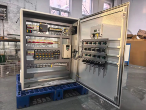
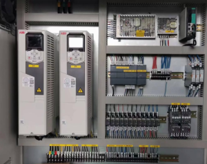
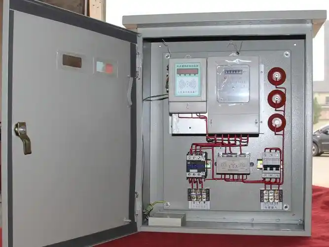
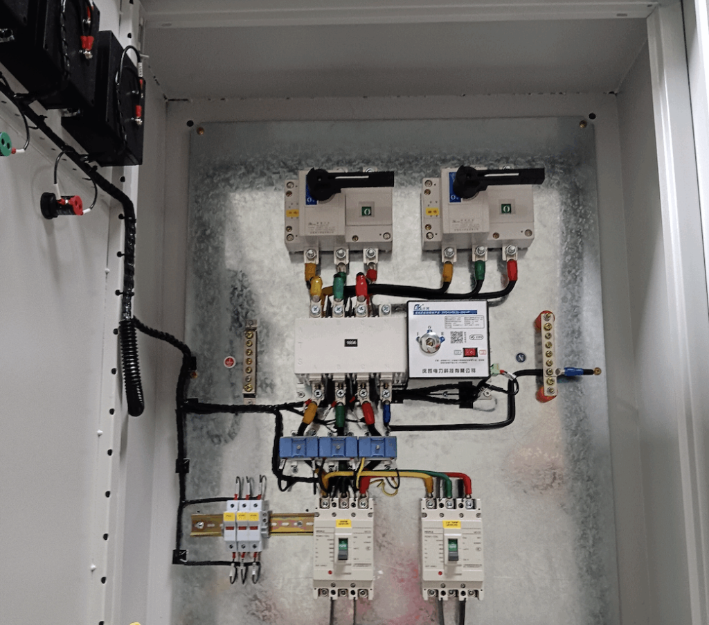
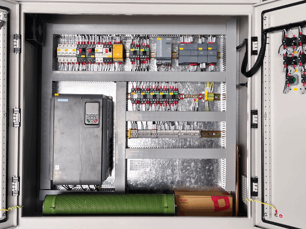
1.2 Key Components
Reliable operation relies on a complete set of matched components that work together to realize control and protection functions.
- Main Electronic Components: Relays, overload protectors, solenoid valves and control switches for power transmission and circuit regulation.
- Sealing Components: Waterproof gaskets, cable glands and sealed wiring ports to ensure water and dust resistance.
- Wireless Control Components: Wireless receiving modules, signal pairing units and delay modules (exclusive to wireless models).
- Safety Auxiliary Components: Limit sensors, earthing modules and fault indicator lights.
2. Main Types and Application Scenarios of Boat Lift Control Boxes
Boat lift control boxes are categorized by control mode, power system and electrical parameters. Different models vary greatly in load capacity and applicable scenarios, so users can select the right type according to their equipment.
2.1 By Control Mode: Wired vs Wireless
- Wired Control Box: Transmits control signals via physical cables. It delivers stable signals with no latency and strong anti-interference capability, free from signal blockage on water. With a low failure rate, it is the mainstream choice for large boat lifts used in fixed docks with frequent and high-precision operation. Its main drawbacks are limited operating range and complicated wiring work.
- Wireless Control Box: Paired with dedicated remote controllers for long-distance flexible operation. It requires no on-site wiring and is easy to install. It is widely used for small yachts, household boat lifts and floating docks. In severe weather, however, signal interference may occur, and regular remote pairing and calibration are required.
2.2 By Power System: Hydraulic, Pneumatic and Manual
- Hydraulic Control Box: Matched with hydraulically driven heavy-duty boat lifts. It provides strong lifting power and hydraulic buffer protection for stable operation, making it the preferred option for commercial docks and large vessels.
- Pneumatic Control Box: Driven by air pressure. It features a simple structure, low maintenance cost and outstanding explosion-proof performance with no risk of hydraulic oil leakage. It is suitable for light-duty boat lifts and facilities at inland freshwater docks.
- Manual Control Box: A basic model operated purely by physical buttons without intelligent modules. It is cost-effective and only applicable to simple small boat lifts for infrequent use on a tight budget.
2.3 By Electrical Specifications: Voltage and Valve Configuration
- 12V/24V Low-Voltage Models: Powered by safe low voltage with low electric leakage risks. They are designed for small yachts and household light-duty boat lifts, requiring no complex power distribution systems.
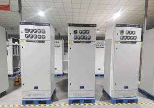
- Standard High-Voltage Models: Used for large commercial and heavy-duty boat lifts. They offer higher power output to lift heavy watercraft.
- 2-Valve & 4-Valve Models: 2-valve units suit single power lifting systems with simple structure and high cost performance. 4-valve units are fitted for dual hydraulic or pneumatic systems to achieve multi-directional precise control, perfect for large and multi-functional boat lift platforms.
3. Buying Guide for Boat Lift Control Boxes
Improper selection is a leading cause of equipment malfunctions. When purchasing or replacing a control box, take equipment parameters, operating environments and safety regulations into full consideration.
3.1 Match Core Technical Parameters
Prioritize parameter matching to avoid incompatibility. For boat lifts with a load of less than 3 tons, choose 12V/24V low-voltage 2-valve control boxes. For loads over 5 tons, select high-voltage 4-valve hydraulic dedicated models. Meanwhile, confirm the original power system type (hydraulic, pneumatic or manual) to prevent short circuits and overload failures caused by mismatched specifications.
3.2 Adapt to Operating Environments
For coastal docks exposed to heavy salt spray, choose marine-grade control boxes with an IP rating of IP56 or above for enhanced rust and corrosion resistance. Standard waterproof models are sufficient for inland freshwater docks. Wired units are recommended for high-frequency commercial use, while wireless models are more convenient for household and recreational boats.
3.3 Comply with Safety Standards
Boat lift control boxes must be equipped with GFCI devices to meet marine electrical safety codes. GFCIs effectively prevent electric leakage and electric shocks in humid working areas and are mandatory for equipment compliance inspection. It is also advisable to select models with overload self-lock, fault alarm and limit protection for all-round operational safety.
4. Wiring and Installation Guide for Boat Lift Control Boxes
Standard wiring and installation are fundamental to stable operation. The whole process must take functionality, waterproofing and safety into account.
4.1 Pre-installation Preparation
Cut off the main power supply completely before work to avoid electric accidents. Inspect the control box for physical damage and check that all sealing accessories are intact. Verify that cable specifications match the equipment voltage and load. Select a dry installation position sheltered from direct rain and excessive vibration, and reserve space for future maintenance. Prepare tools including multimeters, megohmmeters, waterproof cable glands and sealant, and inspect circuits for short circuits and abnormal earthing in advance.
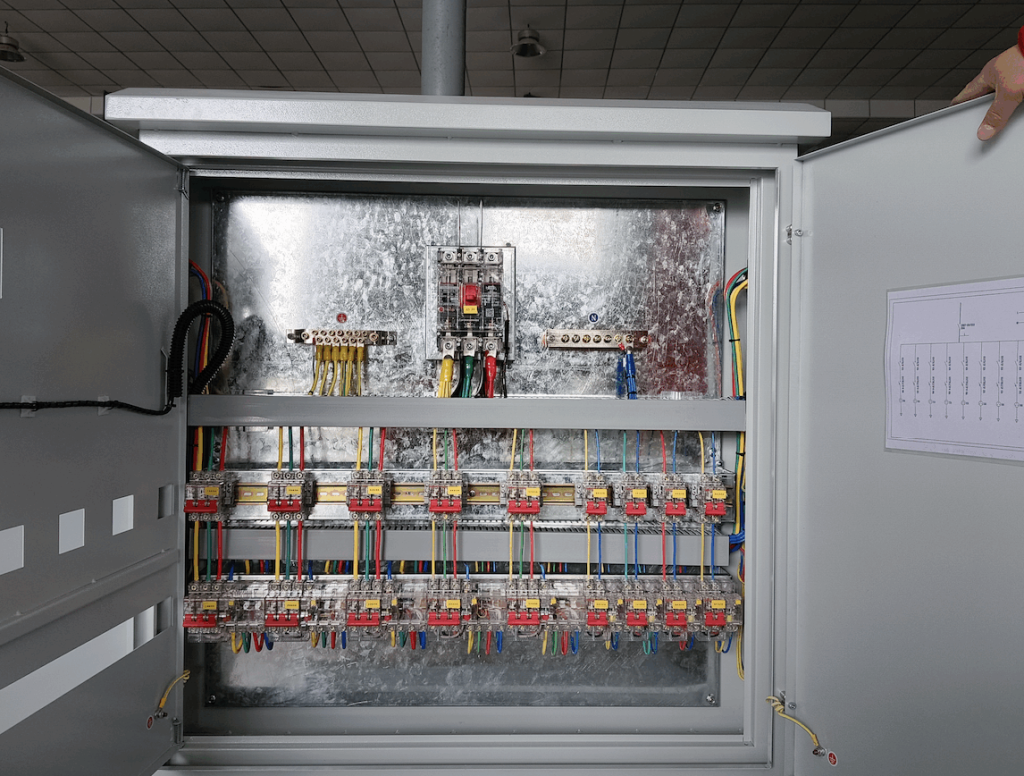
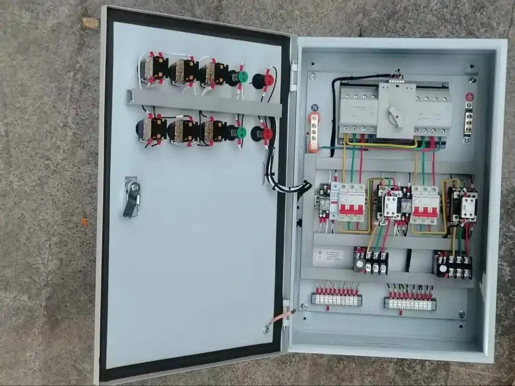
4.2 Step-by-Step Wiring Procedures
- Distinguish power cables, control cables and earthing cables, and connect them to corresponding ports strictly in accordance with the wiring diagram to avoid wrong connections and loose contacts.
- Install waterproof cable glands and apply sealant at cable inlets for full sealing, stopping moisture and salt spray from entering the box.
- Fasten all cables to prevent pulling and abrasion. Ensure the earthing cable is firmly connected to keep the GFCI functioning properly.
- Use a multimeter to test circuit continuity upon completion and troubleshoot short circuits and loose connections.
4.3 Remote Controller Pairing for Wireless Models
Power on the wireless control box, then press and hold the pairing button on the unit for 3 to 5 seconds until the indicator light flashes. Next, press and hold any button on the remote controller. The pairing is completed once the indicator light stays steady. Restart the device and retry if pairing fails, and keep the unit away from similar devices to avoid signal interference.
4.4 Safety Precautions for Installation
All wiring and installation work should be performed by professional electricians in compliance with marine electrical standards. Conduct waterproof tests and GFCI tripping tests after installation to ensure normal protection performance. Fix the unit firmly to prevent loose cables caused by wind and wave vibration. For outdoor installation, add sunshade and rainproof measures to extend service life.
5. Common Faults and Troubleshooting Solutions
Most malfunctions are caused by damp circuits, parameter mismatch, improper operation and component aging. Below are practical solutions for frequent problems.
5.1 No Power and Failure to Start the Equipment
Causes: Power disconnection, tripped GFCI, short circuits due to damp circuits, blown fuses.
Solutions: Check the main power supply and reset the tripped GFCI. Open the box to remove moisture, re-tighten loose and oxidized wiring. Replace fuses with new ones of the same specification and eliminate hidden short circuit risks before re-powering the unit.
5.2 Failure to Lift or Stuttering Operation
Causes: Activated overload protection, faulty limit switches, malfunctioning solenoid valves, insufficient pressure of the power system.
Solutions: Unload excess weight if the load exceeds the rated capacity and restart the equipment. Recalibrate or replace offset or damaged limit sensors. Clean blocked solenoid valves or install new ones to restore normal power output.
5.3 Unresponsive Wireless Remote Controller
Causes: Drained remote batteries, lost pairing, external signal interference, faulty receiving modules.
Solutions: Replace the batteries and re-pair the remote controller. Move the device away from high-frequency equipment to reduce interference. Repair or replace the damaged receiving module if pairing still fails.
5.4 Frequent Tripping and Electric Leakage Alarms
Causes: Damaged cable insulation, water ingress inside the box, electric leakage from aging components.
Solutions: Replace cables with broken insulation. Remove accumulated water and moisture inside the box and reapply sealing treatment. Replace aging faulty components to eliminate persistent electric leakage risks.
5.5 Control Box Reset Operation
Follow the steps below to reset the unit when it locks down due to faults:
- Cut off the main power supply and wait for 3 to 5 minutes to discharge residual electricity in the circuits.
- Identify and fix all faults such as overload, short circuits and mechanical jams.
- Restore power, then press and hold the reset button for 5 seconds. The reset is successful when the indicator light flashes, and the equipment can be restarted for normal use.
5.6 Routine Maintenance Tips
Regularly wipe off dust and salt deposits on the box surface to keep it dry and ventilated. Inspect wiring ports and sealing parts every quarter, and replace aging gaskets and cable glands. Carry out thorough inspections for water ingress and damp circuits after rainy seasons and typhoons. Avoid long-term overload operation to reduce wear of electronic components and prolong service life.
6. Frequently Asked Questions
6.1 What is the main function of a boat lift control box?
As the electronic control core of boat lifts, it controls the lifting, starting and stopping of watercraft. Equipped with multi-layer protection against overload, short circuit and electric leakage, it adapts to harsh marine conditions and ensures stable, safe and compliant operation of boat lifts.
6.2 How to choose a control box with proper specifications?
Make selection based on load capacity, working voltage, power system and operating environment. 12V/24V 2-valve low-voltage models are suitable for yachts under 3 tons, while high-voltage 4-valve hydraulic models are required for loads over 5 tons. Standard waterproof types work for inland areas, and marine-grade anti-corrosion models are a must for coastal regions.
6.3 What are the main reasons for frequent malfunctions?
Common causes include circuit dampness and component corrosion caused by humid and salty air, overload triggering protective locks, tripped safety devices due to loose wiring, short circuits or electric leakage, and aging parts such as limit switches, solenoid valves and receiving modules. You may refer to the above troubleshooting methods for repairs.
6.4 Is a GFCI required for boat lift control boxes?
Yes. Docks and on-water facilities are prone to electric leakage due to high humidity. GFCIs can cut off power instantly once leakage or short circuits occur, protecting personnel and equipment. They are also a basic requirement for compliance inspection.
6.5 Are remote controllers for boat lifts universal?
No. Different brands and models adopt different wireless frequencies and pairing protocols, so dedicated remotes only work with matched control boxes. Remotes from other brands or models cannot be used directly. When replacing a remote, select one compatible with the control box or install a universal pairing module.
7. Conclusion
The selection, installation and daily maintenance of boat lift control boxes directly affect the safety and service life of boat lift equipment. Users shall select proper models according to load capacity, power type and working environment, conduct wiring and installation in line with marine electrical codes, and perform regular waterproof and anti-corrosion maintenance. Follow standardized troubleshooting procedures to resolve faults in a timely manner.
References
- EN 60204-1:2018/A1:2025 Safety of machinery – Electrical equipment of machines
- Technical Standards for Watertight and Explosion-proof Installation of Electrical Equipment on Ship Open Decks
- Codes for Earthing and Electric Leakage Protection of Low-voltage Marine Electrical Equipment