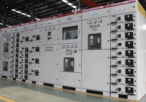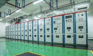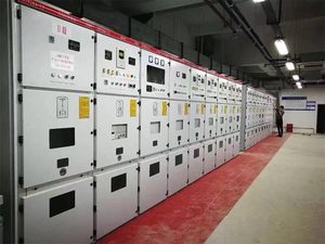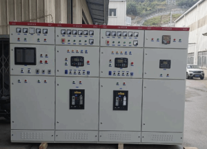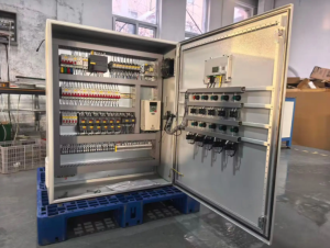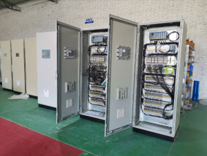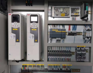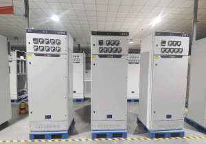
Generator paralleling switchgear serves as the core assembled equipment for complete paralleling systems. It integrates switches, protection units, synchronizing controls and load‑sharing functions to realize parallel synchronization between multiple generator sets, or between generator sets and the utility grid, ensuring stable coordinated power output of multiple units.
This article provides a comprehensive analysis of generator paralleling switchgear from the dimensions of basic definitions, hardware composition, operating logic, core advantages, application scenarios, type‑selection and retrofitting, as well as operation and maintenance risks. It offers technical references for electrical designers, EPC general contractors, equipment purchasers and operation‑maintenance personnel.
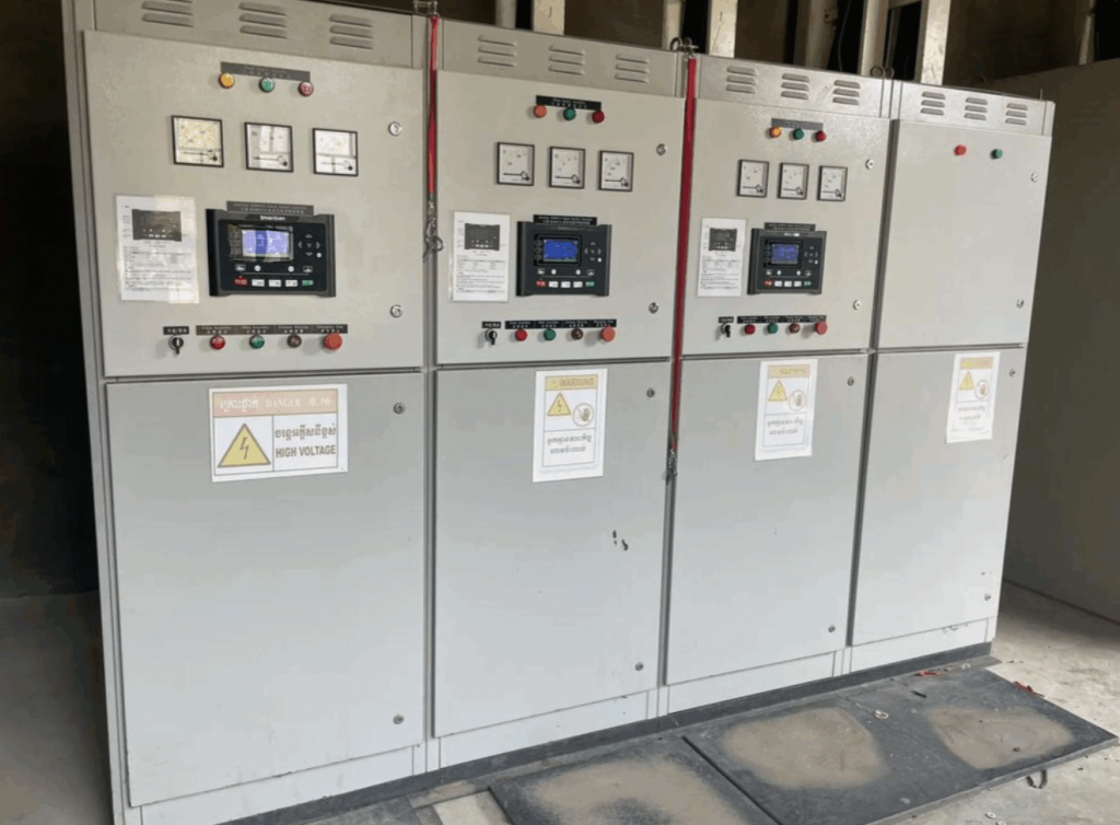
1. What is Generator Paralleling Switchgear
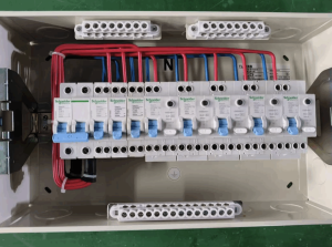
Generator paralleling switchgear is a complete set of power distribution equipment assembled with circuit breakers, relay protection devices, synchronizing controls, load‑sharing modules and measurement & monitoring components. Its core function is to connect multiple generator sets to a common main busbar, complete synchronous closing, and enable parallel loaded operation of multiple units.
Concept confusion frequently occurs in the industry. Three easily‑confused pieces of equipment are distinguished as follows:
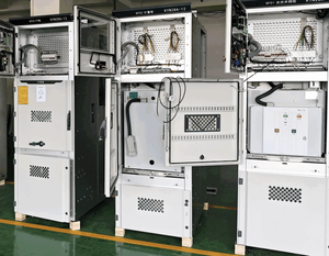
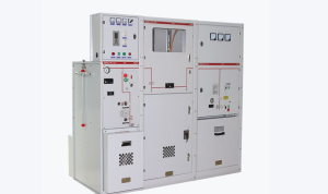
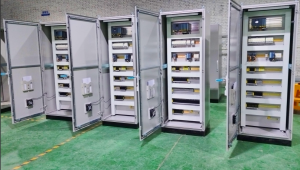
- Generator Paralleling Switchgear: A complete cabinet assembly equipped with main busbars, power circuit breakers, full‑set protection and control systems. It can independently perform paralleling, protection and load management, and is applied for medium‑to‑large‑scale projects.
- Paralleling Switchboard: It delivers functions similar to paralleling switchgear, yet features inferior cabinet structure, ingress protection rating and short‑circuit withstand capacity. It is mostly deployed for low‑voltage small‑and‑medium‑size scenarios.
- Synchronization Panel: It only provides synchronization detection and control functions without high‑power main‑circuit circuit breakers. It cannot operate as a standalone complete power‑distribution system and must work with external switching devices.
Generator paralleling switchgear supports two mainstream operating modes:
- Unit‑to‑unit parallel operation: Multiple generators run in parallel with one another in island mode disconnected from the utility mains, acting as emergency backup power supplies.
- Unit‑to‑grid parallel operation: Generators operate in parallel with the public utility grid to achieve peak shaving and valley filling as well as micro‑grid grid‑tied operation.
2. Component Parts of Generator Paralleling Switchgear
A complete generator paralleling switchgear consists of primary power components and secondary control‑protection components:
- Common Main Busbar: Copper bars where outputs from all generator sets converge to transmit electric power for the whole parallel system. Its rating shall match the system rated current and short‑circuit withstand level.
- Generator‑Specific Circuit Breaker: An independent circuit breaker configured for each generator set for unit switching and fault disconnection, with short‑circuit and overload protection capabilities.
- Synchronizing Controller (ANSI‑25 Synchronizing Device): The core control unit for paralleling. It continuously compares voltage, frequency and phase on both power sides and outputs a closing command once synchronization conditions are met.
- Load‑Sharing Module: Responsible for distributing active and reactive power among parallel generator sets. It supports two control logics: droop mode and isochronous mode.
- Protection Relays: Implement reverse‑power protection, overcurrent protection, differential protection, loss‑of‑excitation protection, over‑voltage / under‑voltage protection, abnormal frequency protection to prevent generator damage caused by paralleling faults.
- Metering and HMI Human‑Machine Interface: Collects operating data including voltage, current, power and frequency, supporting local parameter configuration, status display and fault alarms.
- Load Switching / Load‑Shedding Logic Unit: Automatically sheds non‑critical loads when partial units trip due to faults, so as to guarantee power supply for priority loads.
- Electrical and Mechanical Interlock Devices: Prevent out‑of‑synchronization closing triggered by mis‑operation and protect equipment and personal safety.
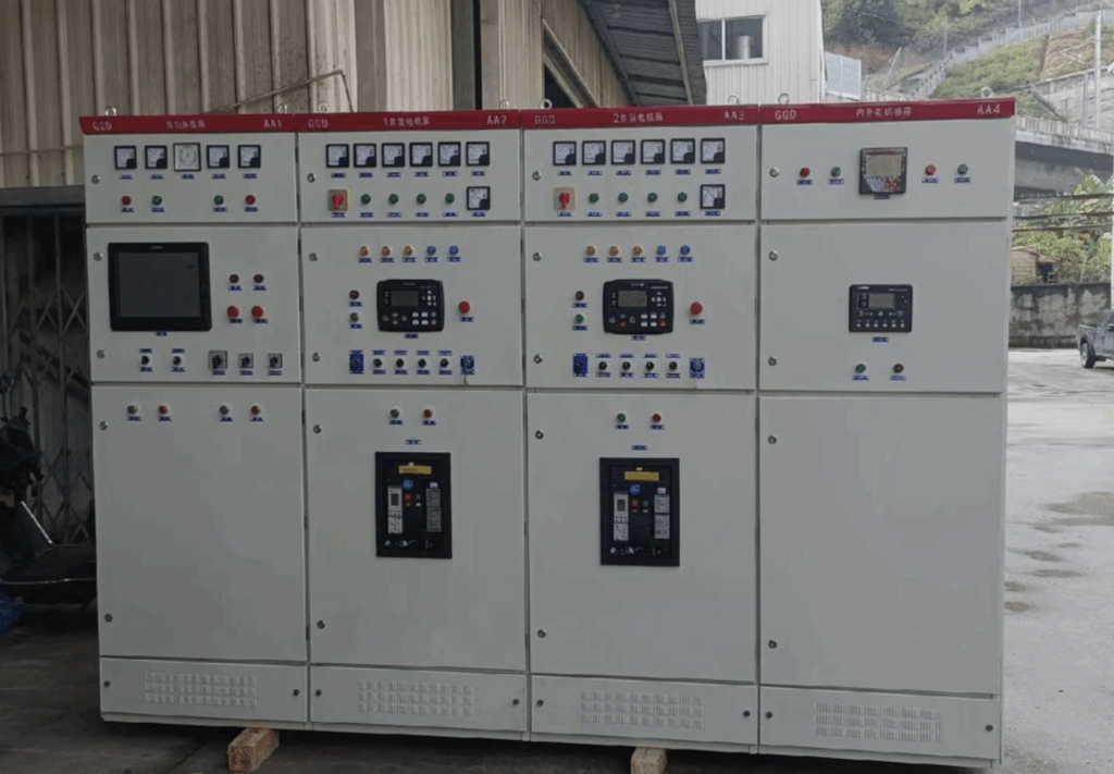
3. Working Principle of Generator Paralleling Switchgear
Four core synchronization prerequisites must be satisfied within allowable tolerance ranges before circuit breakers can be closed for parallel connection:
- Consistent voltage magnitude
- Consistent frequency
- Aligned phase angles
- Identical phase sequence
The full synchronization‑paralleling workflow includes three steps: Step 1: The generator set to be paralleled starts up, accelerates and builds voltage. The synchronizing controller continuously samples power parameters of the standby unit and the energized busbar. Step 2: Adjust the rotating speed and voltage of the standby unit to narrow deviations between the two power sources. A closing signal will be triggered once synchronization thresholds are satisfied. Step 3: The circuit breaker closes to finish grid‑connection. Afterwards the load‑sharing module kicks in and reasonably allocates total load across all paralleled generator sets.
There are two mainstream load‑sharing control modes in the industry:
- Isochronous Mode: The parallel system maintains constant frequency. Suitable for island‑mode backup‑power scenarios. Active power is rapidly redistributed among units upon load variation.
- Droop Mode: System frequency drops slightly as load rises. It fits generator‑to‑utility‑grid parallel applications and long‑term multi‑unit parallel operation.
In terms of power‑switching logic, it is divided into open‑transition and closed‑transition:
- Open Transition: Disconnect the original power source first before engaging the new power source. Short‑term power interruption occurs during switching.
- Closed Transition: Two power sources run in parallel for a short period before the original source is disconnected, achieving uninterrupted switching for critical loads that cannot tolerate momentary power loss.
When one generator set malfunctions within the parallel system, protection relays in the switchgear will rapidly trip the circuit breaker of the faulty unit to isolate it from the busbar. Remaining healthy units keep supplying power to loads. Meanwhile load‑shedding logic will be activated according to the capacity of surviving units to avoid system overload.
4. Selection Guide for Generator Paralleling Switchgear
During scheme design and equipment selection, confirm these key dimensions:
- Determine operating modes: only generator‑to‑generator parallelism, or generator‑to‑utility‑grid interconnection is required.
- Rated voltage class and short‑circuit withstand parameters: match system voltage, calculate short‑circuit current and verify short‑time withstand‑current ratings for cabinets.
- Maximum number of paralleled generator units: confirm quantity of generators to run in parallel on‑site and maximum paralleling capacity supported by controllers.
- Load‑sharing control method: choose between droop mode and isochronous mode.
- Protection configuration requirements: confirm whether reverse‑power protection, differential protection and other functions shall be configured according to generator capacity.
- New‑procurement versus existing‑cabinet retrofitting: evaluate retrofitting feasibility of original power‑distribution cabinets.
- Power‑switching mode: select open‑transition or closed‑transition.
- Local codes and standard compliance: comply with industry standards applicable for project locations.
- Monitoring and communication requirements: check if integration with BMS (Building Management System) for remote monitoring and alarms is needed.
- Budget reference: Equipment cost varies greatly subject to voltage class, paralleling unit quantity, protection configurations and HMI functions. Inquire formal quotations based on complete project specifications.
Frequently Asked Questions (FAQ)
Q1: What is the maximum number of generators that generator paralleling switchgear can parallel?
A: There exists no fixed hardware upper limit. It depends on controller capacity, main‑busbar rated current and short‑circuit withstand rating. In practical engineering, 2‑8 generator units are commonly paralleled for regular projects. Larger micro‑grid projects can support more units with pre‑project system calculation.
Q2: What is the difference between isochronous‑mode and droop‑mode load sharing?
A: The isochronous mode keeps constant system frequency and is mostly used for island‑mode backup power supplies. The droop mode allows minor frequency drop with load increase and is suitable for grid‑tied generator applications.
Q3: Are generator paralleling switchgear and synchronization panel the same device?
A: No. A synchronization panel only handles synchronization control without main power‑circuit breakers. Generator paralleling switchgear is a complete assembled power‑distribution system containing primary power circuits.
Q4: What is the approximate cost of generator paralleling switchgear?
A: Prices vary significantly depending on voltage class, quantity of paralleled units, protection configurations and communication functions. There is a multiple‑fold price gap between low‑voltage small‑capacity systems and medium‑to‑large‑capacity complete assemblies. Obtain formal quotations from manufacturers with full project parameters.
Q5: Can multiple generators be paralleled directly without generator paralleling switchgear?
A: It is strongly discouraged. Direct hard‑parallel connection lacks synchronization detection, protection and load‑sharing controls. It may easily trigger out‑of‑synchronization closing and reverse‑power damage to generators, which counts as high‑risk non‑compliant operation.
Summary
Generator paralleling switchgear acts as the core assembled equipment for multi‑generator parallel power‑supply systems. It delivers N+1 redundancy and flexible capacity expansion as well as offline maintenance capability via synchronizing control, load‑sharing and comprehensive relay protections. It is critical equipment for high‑reliability power‑supply projects such as data centers, hospitals, industrial plants and micro‑grids.
If you intend to purchase generator paralleling switchgear, please contact FUKEN.
References
- NFPA 110‑Standard for Emergency and Standby Power Systems
- IEEE 1547‑Standard for Interconnection and Interoperability of Distributed Energy Resources with Associated Electric Power Systems Interfaces
- UL 891‑Switchboards Safety Standard